

 |
I’ve seen this infographic (at right) posted several times on the internet. My inner engineer couldn’t help but to tinker with it and give it that little something extra[0]. I’ll dial it up to ’11’ by making it useful without writing a dissertation on each subject. Here goes…
“Nice one. Okay, we’re going to assume that you’re on Earth and you can read English. So far, so good.”
I’m not sure why the author is concerned about your reading language changing as you time travel, but there are all sorts of interesting time travel paradoxes. I’ll mention two that I find interesting.
- Your time machine might just appear in the middle of space. Unless your time machine is also a spaceship, it might make for a very bad (and short) day. If you were transported in time ONLY, you might find yourself a long way from anything. The Earth is moving around the sun which is moving around the galaxy. Where the Earth is today is not where it was 1000 years ago. So you are on a spaceship except it doesn’t have a cool holodeck. (Seriously, who would ever leave the holodeck if you had one?)
- You might not have free will. If you only travel a few years into the past and both ‘past you’ and ‘present you’ can exist at the same time, do you lose your free will as soon as duplicate you appears? Because now that duplicate you exists, you can’t change your mind about entering the time machine. (Or are you now invincible because you can’t die before you enter the time machine? If you travel back just one day, are you in your own mini-version of the movie Groundhog Day?)
“First, we need some units. But no biggie. The exact speed of light in a vacuum is 299,792,458 meters per second. Good to know. A meter is defined in terms of light, but if you can’t measure it accurately, the length of a pendulum that takes one second to swing from end-to-end will do the trick. Pendulums tend to take the same amount of time to swing regardless of how high you start them off. So don’t worry about that. Pretty neat, right? Galileo discovered that. But whatever take the credit. If you don’t have a watch, a second is about how long it takes to say ‘one Mississippi’. And a gram is pretty much the weight of one centimeter cubed of water.”
We don’t need units! Meters, seconds, and grams are all just arbitrary. There is nothing special about them other than we have agreed on them in order to communicate with each other [1]. Knowing the exact speed of light in our arbitrary units is far less important than knowing that the speed at which electromagnetic waves travel in a vacuum is constant everywhere in the universe. We didn’t figure that out until the 20th century. That fact isn’t very helpful rebuilding civilization (the Amish seem to be doing fine without it), but we are counting on it for communicating size with alien civilizations [2].
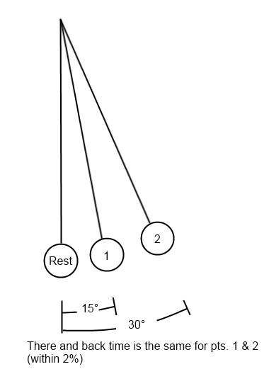 |
It’s true that a pendulum takes approximately the same time to swing there and back as long as you don’t pull it back more than 30° from rest. The pendulum’s behavior was behind the world’s most accurate timekeeping technology until we developed better technology in the 20th century.
Accurate time keeping is important for navigation and communication, which will be addressed later, but most of civilization could be rebuilt with a simple sun dial or no time keeping device at all.
“Flight: The wing took a long time to figure out. Just remember aerofoils are objects shaped such that air above them progresses faster than air moving beneath them. Slower moving air has more pressure. So there is a net upwards force.”
This is alluding to a common myth called “equal transit time” along with the Bernoulli principle [3] to describe how an airfoil works. So as not to bore you with the details of the equal transit time theory, I’ll leave it in the endnotes [4] but if this theory were true then planes would not be able to fly upside down.
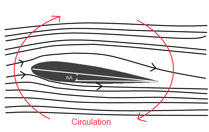 |
Symmetrical airfoils (like the one depicted at right) wouldn’t work either but rest assured that they do. It’s not to say that the airfoil shape doesn’t affect the lifting force, but it doesn’t do so in the way described, nor is the airfoil shape essential for flight. A barn door could be used as a wing and it would create lift under the correct circumstances. A wing must:
- Change the direction of the incoming air, deflecting it downwards from both the upper and lower sides of the wing. If the air is deflected downwards, an equivalent force acts on the wings upwards. The angle of attack affects this force greatly.
- Induce circulation around the wing the net effect of which is a low pressure pocket above the wing. This pressure difference results in lift (Bernoulli principle).
These two are the major factors affecting lift. That being said, a barn door has many undesirable characteristics as a lifting surface. The point being that an airfoil-shaped wing is more desirable but it isn’t essential for flight.
Note the angle labeled as AA (angle of attack) in the graphic. That’s going to be important in a moment!
“Attach an aerofoil of sufficient size to a machine capable of moving itself forward fast enough and it will fly. You can make a plane by attaching two aerofoils to a central body, add flaps at the trailing edge and you can control where it goes.”
There is essentially nothing wrong with these two sentences other than they try to distill more than 100 years of aeronautical research into two sentences. I can’t do it much more justice in a few pages, but I can use the totally awesome example of the Colditz glider and the work of the Wright brothers to introduce 4 things you should know if you are going to reinvent heavier than air flight. (Nerd warning! I probably got a bit carried away in this section so if it starts to get too deep for you just skim the bolded sections.)
The Colditz glider was a glider built by British prisoners of war to escape from Colditz Castle.
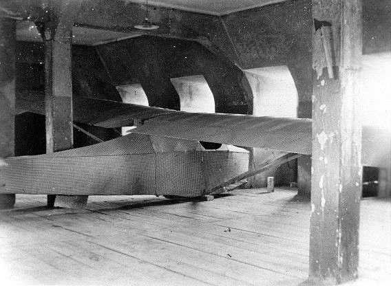 |
Imagine building a glider from bed slats, floor boards, sleeping bags and millet rations used as a dope. Imagine launching it from the roof of the castle’s chapel using a pulley system that relied on a falling metal bathtub full of concrete. There are no test runs. You will live or die based upon how well it is engineered and constructed. It’s the ultimate acid-test for engineering. Do you really understand the engineering principles behind flight? How do you know the gliders wings will provide enough lift to float you 220 meters across the river to safety? That’s the first of our 4 things to understand while reinventing the airplane: Lift.
#1.) Lift is the force that makes a plane different from an automobile. Four fundamental forces act on an airplane; lift, gravity, thrust and drag. Thrust from the engine drives it forward, drag from the air slows it down and gravity tries to keep it on the ground. Understanding how lift occurs and how it can disappear (stall) is key to flight.
Lifting force is dominated by the relative speed of the air over the wings and the surface area of the wing.
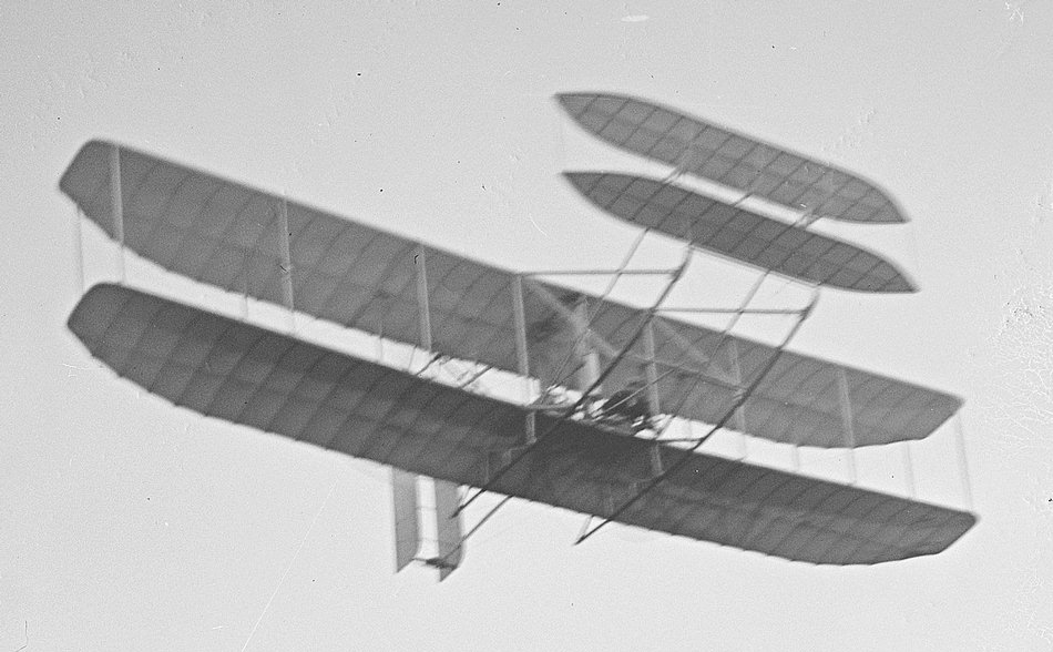 |
Notice the design of the Wright brothers’ plane. Why did they use two main wings instead of one? The answer is to get sufficient lift. If we look at the equation for lift, we can see that air velocity is by far the most important term followed by the surface area of the wing. If you double the velocity you get 4 times as much lift but if you double the wing area you only get twice as much lift.
Lift=0.5·ρ·V2·A·CL
- ρ is the density of air (mostly constant for low altitudes)
- V is the relative velocity of the air over the wing.
- A is the projected area of the wing (the area it has looking down from the top)
- CL is the coefficient of lift that is determined by the cross-sectional shape of the airfoil and its angle of attack. Its range of value is roughly 0 to 4 for modern aircraft and 0-1 for early planes.
The Wright brothers needed lift at low speed because their low power engine limited the speed at which they could fly. Construction materials at the time weren’t strong enough to create a large single wing so they used a bi-wing design to get more wing area. The lift equation was well known to the Wright brothers and they used it extensively.[5] They didn’t just randomly make wings and try them. They used careful observation and the lift equation to tell them what size and shape wing they needed. This is exactly what the engineers behind the Colditz glider were forced to do. There were no trial runs.
Let’s plug in some numbers from the glider and see how it would have fared.
The glider weighed 240lbs (109 kg) empty. If you add 2 passengers each weighing 155lbs (70.5kg) then we are up to 550lbs (250kg) total. The glider must have at least 560lbs of lifting force (2491 N) or it won’t be gliding but rather falling (possibly with style). We know the glider had a wing area of 162 sqft (15m2). I’m going to switch to metric units at this point to make my calculations easier. Assuming an air density of 1.2 kg/m3 and a CL of 1.4 which is in line with the Clark Y-H airfoil performance data, and plugging these values into the above lift equation we get this:
2491 N = 0.5 * 1.2 kg/m3 * V2 * 15m2 * 1.4
Solving for V, we get 13.9 m/s (31 mph) as the minimum speed to provide enough lift. So the bathtub full of concrete has to catapult the glider up to that speed or it will be a very short flight. That is the stall speed that the engineers calculated and expected from the glider. If the engineers of the glider needed to launch at a slower speed, they would have been forced to increase the wing area of the glider (which also adds to its weight). They might have gone with a bi-wing design like the Wright brothers if they doubted the strength of the construction materials to build a larger single wing.
So why don’t we see bi-wings on modern aircraft? It is because modern planes fly much faster, roughly 20 times faster than the Wright brothers’ plane. That’s 400 times (202) more lifting force due to the increased air velocity over the airfoil. Flying faster has its advantages but it makes takeoff and landing more interesting. That’s because a plane designed to fly 500 mph may need to get to 200 mph just to get enough lift to take off (Ignore the use of flaps for the moment. I’m going to get to that) Faster takeoff and landing speeds require longer and smoother runways. Landing a plane at 200 mph in a plowed field or on a lake isn’t going to be a pretty thing. You can’t just land slower because the minute you drop below 200 mph you are no longer creating enough lift to counteract the force of gravity and the plane starts losing altitude. The farther you get below 200 mph the more the plane drops like a rock. Not that you will have to worry about landing at high speed while you re-invent the airplane because you will be in the same position as the Wright brothers – limited by construction materials and low power density engines.
Lift can be increased with the use of moveable flaps. An area where you could get a huge jump on the Wright brothers is by understanding and using moveable flaps. Have you seen the flaps that extend out of a modern plane’s wings on take-off and landing?
 |
Modern aircraft use flaps and slats to modify the shape and area of the wing while the aircraft is in-flight. It increases the wing’s coefficient of lift and wing area so that the wing produces more lift at a slower speed. This gives the aircraft a slower stall speed. To understand why flaps and stall are important we need to look more closely at how the coefficient of lift term changes (It’s the last term in the equation above).
The CL term is where lift gets interesting because it introduces stall (loss of lift). If you are only going to remember one thing about the CL term, let it be the general shape of its curve and that it has a stall point. The value of the CL term changes with the angle of attack and the shape of the airfoil. The Wright brothers used a homemade wind tunnel and test jig to map out how CL changed as the angle of attack changed for different airfoils. The testing jig the Wright Brothers built is a beautiful piece of engineering. It was simple, elegant and functional. The Wright brothers were amazing engineers without a high school diploma between them. They used careful experimentation, thorough research and hard work to beat their competitors to building the first plane. Alas, I don’t have space in the main article to cover their test jig so it gets relegated to the endnotes [6] (Real nerds read endnotes anyway and, trust me, if you have read this far you are a REAL nerd).
#2.) Understanding what stall is and how it occurs is important to reinventing heavier than air flight. It is easiest to explain with a visual aid. This chart depicts the performance of the shown symmetrical airfoil.
 |
Note how the value of CL (red line) increases with the angle of attack from 0 to about 22° then it decreases rapidly. Twenty-two degrees is the stall angle of this airfoil. Increasing the angle of attack further will only reduce the lift it produces. Imagine an inexperienced pilot trying to take off on a runway with trees at the end of it. The pilot wants the plane to climb quickly to avoid hitting the trees so the pilot keeps pulling the stick back effectively increasing the angle of attack on the airfoil. This generates more lift until the stall angle is reached and after that pulling back on the stick reduces lift. To make things worse, the drag created by the airfoil (purple line) keeps increasing with the angle of attack. If the engine isn’t powerful enough to overcome this additional drag the plane slows down and that results in even more loss of lift. Since relative air velocity over the wing is the most important term in the lift equation, loss of velocity is devastating. The plane will start to drop out of the sky much like a brick would. The only way to recover is pitch the nose the plane down thus reducing the angle of attack and try to increase the air speed. While you are waiting for your airspeed to recover, you are falling out of the sky. If you don’t have enough altitude to wait for this to happen, you crash into the ground.
So back to those flaps that extend out of the wings of modern airplanes. Moveable flaps radically change the shape of the coefficient of lift curve. They allow the airfoil to create a larger coefficient of lift at a higher angle of attack without inducing stall.
 |
This means that the aircraft can take-off and land at a much slower speed than it would when the flaps are retracted into the wing. So why not just leave them out all the time? Because they also radically increase the drag on the airfoil so it would be very inefficient to fly with them extended. Modern airplanes designed for short take-off and landing use this technology extensively. If you had to reinvent the airplane, knowing what flaps are and why they work would be incredibly helpful.
#3.) 3-axis control is the way to go!
 |
Three axis control is achieved by using lifting forces to control how much the aircraft pitches, rolls or yaws. Early pioneers like Otto Lilienthal tried to use the shifting of their body weight to control their gliders (much like modern hang-gliders do). Let’s look at how that works and why it is impractical for anything other than ultra-light aircraft.
Every aircraft is going to have a center of gravity (CoG) where all the gravitational forces can be summed into one representative force. Each aircraft also has a center of pressure (CoP). That is the point where the various lifting forces can be summed up into one representative force.
 |
 |
Forces lined up. There is no twisting force and the aircraft is stable in the pitch axis.
Forces causing the nose to pitch down.
 |
Forces causing the nose to pitch up.
Otto Lilienthal relied on being able to shift his body weight forward or backward as well as left or right enough to move the center of gravity of the glider to induce a pitch or roll in the desired direction. That’s how modern hang gliders work. It should be obvious why this wouldn’t work on a commercial aircraft. Can you imagine passengers running around inside the plane in an attempt to move the CoG enough to get the aircraft to pitch or roll in the correct direction? Unfortunately, Otto Lilienthal was killed when a gust of wind forced his glider’s nose up. This pushed the angle of attack of the wing into the stall region. Lilienthal was unable to shift his weight enough to get the CoG in front of the CoP which would have caused the nose of the glider to pitch down. Thus the glider was stuck in this stalled condition and it plummeted to the ground.
Use control surfaces to achieve 3-axis control. The Wright brothers, obviously wanting to avoid the same scenario, decided to use control surfaces to adjust pitch, roll and yaw instead of shifting their weight. By doing this, they moved the CoP to control the aircraft instead of moving the CoG as Lilienthal had done. What is a control surface? It is a small wing in which the lifting force is used for control.
|
|
For example, the Wright Brothers used a set of smaller wings, out in front of the main wings, to control the angle of attack of the main wings. When they wanted the plane gain altitude, the angle of attack on the smaller wings was increased via a lever. This increases the lift they produce and that lift pitches the nose of the plane up. This increases the angle of attack of the main wings which causes them to produce more lift. The Wright brothers purposely used this configuration because it offers a friendlier stall. If pilot error or a gust of wind causes the front wings to stall, it will result in a rotation that forces the nose down. This works to keep the main wings from stalling by reducing their angle of attack. As long as the front wings stall before the main wings stall it keeps them out of trouble. Thus it makes it much harder, but not impossible, to get into a death stall like the one that killed Lilienthal.
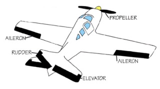 |
This idea of a control surface is used to control the rolling and yawing of the plane as well. On today’s planes, most of the control surfaces are on the tail of the plane. The elevators control the pitch. The rudder controls the yaw and the ailerons which are located on the main wings control the roll.
#4.) Stable response to an upset keeps you out of trouble. The Wright flyer was an unstable and twitchy plane that the Wright brothers managed to fly only because of their extensive practice. Their canard configuration worked well in avoiding stall but under normal operating conditions it required lots of pilot input to maintain steady flight. It’s because, at that time, no one was considering the effect of the pitch, roll and yaw moments of the aircraft.
If you look back at the airfoil chart, you can see the line marked c.p. for center of pressure. The CoP moves as the angle of attack moves but for a symmetrical airfoil it is fairly stable and in this case it moves only slightly towards the trailing edge after the stall angle is reached. Some airfoils have much more radical shifts. That movement causes a moment (twisting force) the father it gets from the CoG. The Wright brothers didn’t really consider that it moved, or how far it moved, or how quickly it moved.
If you consider moments about the 3-axes when designing the plane you will have a much more stable plane. Here is an example: If you move the CoG forward of all lifting surfaces, which is where it is in modern planes, then when there is a disturbance (like a gust of wind) it increases the lift forces on the wing and tail. This will produce a rotation that forces the nose down, tending to decrease the angle of attack and restore the initial state. This is a stable response. It takes into account how disturbances affect the pitch moment. The Wright brothers’ plane had a CoG that was between the control surface and the main lifting surface. Any disturbance would require pilot input to stabilize.
That’s the basics of flight. It’s hard to cover more than that without writing a book and many fine books have already been written on the subject. I completely skipped over the part where you invent the internal combustion engine and then make it light enough and powerful enough to attach to a plane but lift, moveable flaps, stall, 3-axis control and stable response should go a long way in keeping you alive long enough to reinvent the plane should you solve the high power density internal combustion engine problem. Good Luck!
“Heat milk to just below its boiling point: It won’t curdle and 99.999% of the bugs in it will be killed. Congratulations! You just invented Pasteurization.”
This is technically correct for large values of “just below boiling point”. Modern pasteurization uses high temperature and short time to kill pathogens in the milk. It kills off the most heat-sensitive pathogens while retaining the qualities of milk that consumers expect. This amounts to heating the milk to 161° F (72° C) for 15 seconds by running the milk through a tube of which the size and diameter takes the milk exactly 15 seconds to pass. Since that may be a bit more sophisticated than possible with primitive technology, you can also batch pasteurize the milk by heating it to 154.4°F (63° C) in a large container and holding it at that temperature for 30 minutes while it is stirred continuously. Americans would find it strange to walk into a store and purchase a bottle of milk that has been sitting on the shelf unrefrigerated for months but in Spain this is a common occurrence. The milk has been ultra-high temperature pasteurized by heating it to 280°F (138°C) for a minimum of two seconds. Milk pasteurized in this manner may be stored unrefrigerated for 6-9 months (using sterile packaging of course).
Pasteurization is one of the more mild forms of thermal processing and it works by denaturing the enzymes in the bacteria. The original author didn’t talk about it but canning of food works similarly. It wasn’t until the early 1800s that we figured out how to preserve food by canning. If you are reinventing canning, you will need sturdy, air tight containers in which the food could be heated. How long and to what temperature the food needs to be heated depends upon the acidity of the food. Low acid foods must be heated more than high acid foods because the acid helps to denature the enzymes of the bacteria. You will need a pressure canner to sufficiently heat some foods. An open pot of water won’t get hotter than 212°F (100 °C) no matter how long you boil it. A closed pot in which the pressure can build allows you to heat the food to temperatures of 250°F (121°C ) for the 20 to 100 minutes it will take to kill bacteria in low acid foods. The most worrisome danger of canning is not killing C. botulinum spores. C. botulinum is a bacterium that thrives in the low oxygen, high moisture environment of the can. It releases a toxin that is among the most lethal toxins in the world. The toxin is odorless, colorless and tasteless. An amount equivalent to a quarter of a grain of sand (75 nanograms) is enough to kill a person. The good news is that, while the C. botulinum can survive boiling water, the toxin it produces breaks down with temperature. Heating canned food to a typical cooking temperature of 176°F (80°C) for 10 minutes before consumption can greatly reduce the risk of illness. Personally, I would make sure that the food was cooked enough to kill C. botulinum in the first place. So in a nutshell, canning is using heat and acid to reduce pathogens to a level that allows the food to be eaten years later (assuming proper storage – meaning cool temperatures and a good seal on the jar).
“A moving electric field produces magnetism, and vice versa. Wrap copper wire around an iron core and run electricity through it and you’ve got an electromagnet. Don’t have any electricity? Put a magnet on a water wheel and put your copper-wrapped iron beside the wheel and hey presto, you’re converting mechanical energy into electricity. Don’t have any magnets? Heat iron to get a very weak one. Look for black grains in beach sands that stick together or examine the sites of lightning strikes for magnetic lodestones.”
This glosses over an interesting Catch-22 in using permanent magnets to generate electricity. It is true that the majority of the today’s electricity is generated by moving conductors through a magnetic field but the strength of the magnetic field needed to create any practical amount of electricity is far stronger than the field produced by a lodestone. Beach sand or heated iron isn’t going to cut it either [7]. Today’s magnets are manufactured by using large electric currents. So you need electricity to make a strong magnet but you need a strong magnet to make electricity. That’s the Catch-22. Luckily there is a way around this dilemma. (I’m skipping how to make a permanent magnet but if you really want to know see this video http://www.youtube.com/watch?v=noGGcyPHtdI)
Instead of trying to making a permanent magnet, a much more practical approach would be to make a primitive battery and use it power an electromagnet. Then use the electromagnet in place of the permanent magnet in your generator. Some of the electricity generated is then fed back to the electromagnet and once the generator is going the battery can be completely disconnected. Of course if the generator ever stops then the whole process must be repeated. This is technically called using external-excitation to induce self-excitation in field coils in a generator. Self-excitation is how the majority of large generators, like the ones used in modern power plants, function. They don’t use permanent magnets but rather they power an internal electromagnet with some of the electricity they generate.
Forgive me for skipping over the details of how to build a primitive battery. I’m struggling to cover the topics the original author covered without deviating too much on to side topics. But if I were trying to reinvent the battery I think I would start with a Voltaic pile. It was the World’s first battery and it uses copper, zinc and cloth soaked in brine. My second choice would probably be a lead-acid battery. Both will have interesting challenges in trying to round up the raw materials needed to make them.
Let’s quickly look at how an electromagnet works and why not just any copper wire is going to work and how electricity is generated by moving conductors through a magnetic field.
Moving electrons create a magnetic field. It is much like how a moving boat creates a wake.
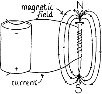 |
So any conductor that has electrons flowing through it has a magnetic field around it. Normally this field is very weak (compared to modern magnets) but it can be intensified by wrapping lots of coils of wire in a small space and if the coils are wrapped around something ferromagnetic, like a piece of iron, then the magnetic field is focused. This is how you create an electromagnet. But it can’t just be any copper wire – bare copper wire wont’ work. The wire needs a thin coat of insulation. Insulation is what keeps the electrons flowing through all the coils instead of taking the short cut from the first coil to the last coil. Modern copper wire for use in windings has a thin layer of enamel that insulates the wire and avoids short circuits. Any non-conduction insulation will work but it needs to be thin because a thick insulation will limit how many coils of wire you can wrap in a small space. Have you ever “burned up” an electric motor? This happens when the motor gets too hot and the insulation melts and allows the electricity to take a short cut. This short cut reduces the strength of the magnetic field so much that the motor no longer functions.
Rather than go into the details of how generators and motors work, I will just direct you to this excellent video that every time traveler should watch. If you don’t understand how to build a decent DC motor or generator after watching it, then you probably shouldn’t be messing around with time machines.
“Run electricity through tungsten to get the light bulb.”
A carbonized bamboo filament was used before tungsten but it was fragile and not as bright. If you are reinventing the light bulb, you have a much better shot at inventing it than a tungsten filament. Tungsten is far too brittle to be used in its natural state and it won’t last long unless it is in a vacuum or, even better, surrounded by argon gas. The real engineering feat is the process by which tungsten is made ductile. I’m going to pull this excerpt from an Engineer Guy video on the subject to illustrate the difficulty. In an abbreviated list of steps to make the tungsten filament you would need to:
 |
1. Apply great pressure to turn the tungsten power into a fragile bar.
2. Heat the bar to 1300 °C and then cool it with water.
3. Pass current thru the bar while heating it to 3200 °C and then cool it again.
4. Heat it again to 1500 °C while flowing hydrogen gas over it.
5. Pass it through a series of dies and cold work it.
6. Heat it and then reduce temperature while drawing it out into a 1mm wire.
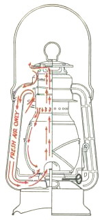
It is safe to say that it will be extremely difficult to reinvent the tungsten filament light bulb. You would be better off inventing something like the cold blast hurricane lantern (shown right). It’s brighter and safer than using a simple open flame and it is relatively simple. Light bulbs were an essential step toward bringing electric light to the masses and they certainly are ubiquitous today but are they really an essential step in rebuilding civilization? I don’t know the answer but if there is one place I am grateful for electric lighting it would be the surgical theater. I want my surgeons to clearly see what they are doing.
“Run electricity back and forth along a wire with enough power and you’ve invented radio. When a radio wave interacts with a receiving antenna, the exact same electrical charge can be recovered. Information can be encoded in two ways: In the charge of the electricity (higher current produces a higher amplitude) or in the frequency of the electrical reversals. FM is more resistant to amplitude decay in transit.”
Electricity running back and forth in a wire does create electromagnetic waves but just increasing the power doesn’t make it radio. Before discussing radio waves and how to create them, I want to point out that if you understand the theory behind creating radio waves, you will understand how to create micro waves or X-rays.
What are radio waves?
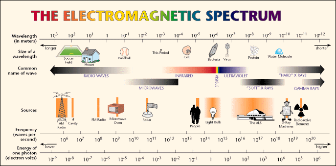 |
They are electromagnetic waves just like X-rays, gamma rays, micro waves, and light waves. You could say radio waves are light waves that have a color so far below red that we can’t see them. Normally we refer to light as slice of electromagnetic spectrum that our eyes can detect but really the difference between all of these waves is their frequency and energy. Higher the frequency waves have a shorter wavelength and they also have more energy. X-rays have so much energy that they strip the electrons off of atoms they encounter and leave the atom with a positive charge. This ionizing radiation has unhealthy effects in most living creatures. That effect is what we normally think of when we hear the word ‘radiation’. All of these waves are called electromagnetic radiation because they don’t require a medium in which to propagate. They can travel through empty space unlike sound waves which require something (like air) to travel through.
How do you create electromagnetic waves? Anytime a charged particle accelerates it creates electromagnetic waves. So the original author is correct in that electrons (a charged particle) running back and forth in a wire (changing direction requires acceleration) create an electromagnetic wave. The frequency of this wave is dependent on how fast they are changing direction. If you can set up an alternating current of 600,000 cycles per second, then an electromagnetic wave with the same frequency of 600 on your AM dial will be created. However, it would be very weak without the aid of resonance and an antenna to help broadcast the wave. I’ll explain better as I cover the early transmitters.
The first radio transmitters were spark gap transmitters. They are very simple and they make a good place to start discussing basic principles.
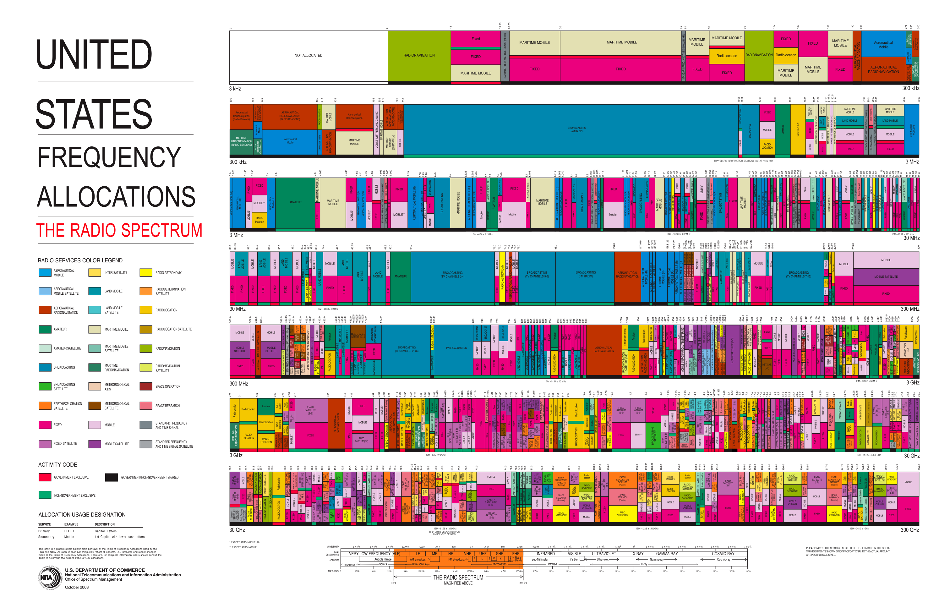 |
Before we go into how they operate, it should be mentioned that they are illegal to operate everywhere in the modern world. It’s because they transmit over a wide range of frequencies and thus interfere with the transmissions on other frequencies. Shortly after radio was invented, we had to create governing bodies to fairly allocate the spectrum of transmission frequencies. If you look at this chart of modern frequency allocation, you can see why wireless companies are willing to spend millions or billions of dollars to get a slice of frequency. The allocations get crazy around 1GHz because the signals can penetrate obstacles and there is enough bandwidth to transmit lots of data. So you can see why a transmitter that transmits over several gigahertz will make many people unhappy. Bottom line: Operating a spark gap transmitter is a very bad move and a federal crime. Even if all your friends are doing it, just say ‘No’.
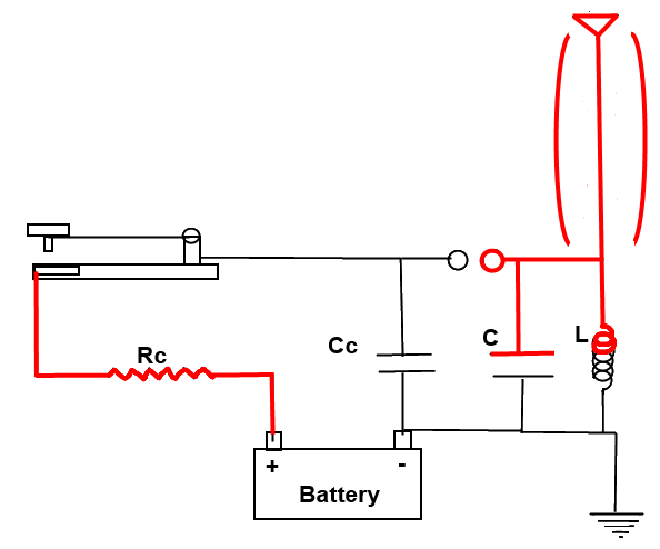
How to build a radio transmitter:
Here is a very simple spark gap radio transmitter. It is the most basic tranmitter you can create. Let’s look at how it operates.
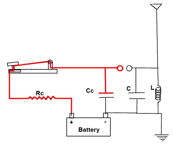 |
1. When the telegraph key is depressed, it forms a complete circuit and the electricity from the battery flows through resistor Rc into capacitor Cc. The charge on this capacitor starts to rise.
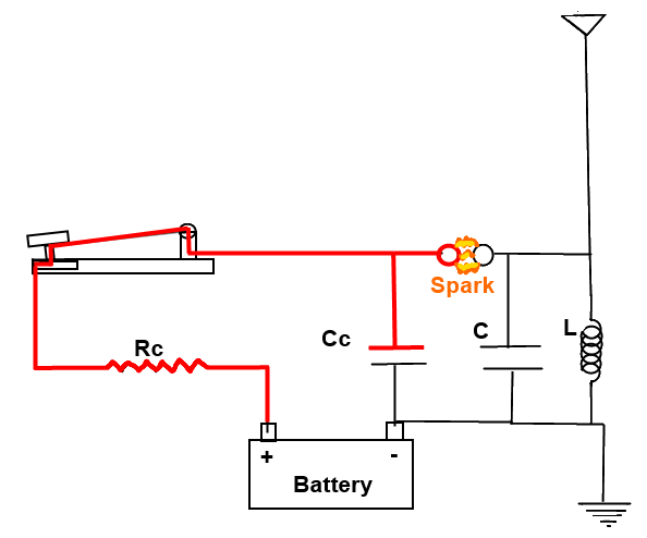 |
2. In just milliseconds, the voltage of Cc rises to a level where current will arc across the spark gap.
3. The spark ionizes the air forming a conducting path that allows the charge in capacitor Cc to rush across the gap into capacitor C.
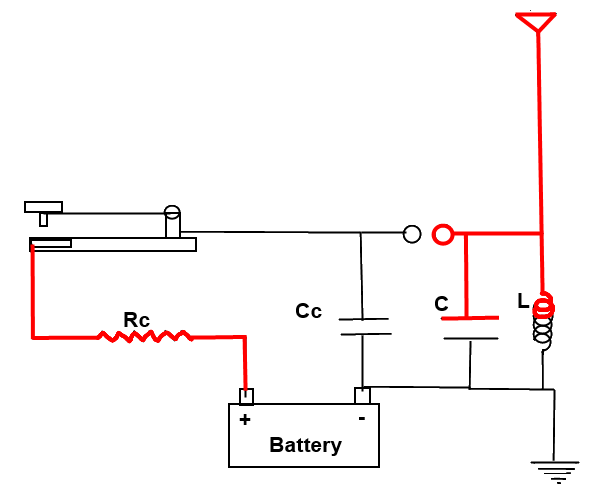 |
4. The coil “L” and capacitor “C” along with the resistance “R” of the circuit make up a resonator. A resonator an elemental electrical circuit that will “ring” or resonate at a specific frequency when exposed to the proper electrical impulse. This is analogous to a bell being struck with a hammer.
5. The surging current coming across the spark gap acts as such a hammer. It starts the LCR circuit oscillating. During the oscillations, the voltage on the upper terminals of the inductor and capacitor switches back and forth between positive and negative until the oscillations are damped out by the effects of the resistance and radiation losses.
6. The voltage in the antenna is forced to oscillate at the same frequency of the LCR circuit since it is connected to the circuit.
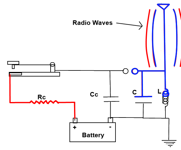
7. The antenna needs to be a specific length so that a standing wave is set up in the antenna. This is like sizing a bell so that it will ring at a certain frequency. This greatly increases the efficiency with which the antenna radiates. The length of the antenna needs to be ¼, ½ or 1 wavelength of the frequency you want to broadcast. So for 600 kHz that would mean an antenna of 410ft, 820ft or 1640ft (125m, 250m or 500m).
8. Oscillating voltage in the antenna sets up an alternating magnetic field around the antenna. The alternating magnetic field will in turn create an alternating electric field in space further out from the antenna. That alternating electric field will create another magnetic field farther out which creates another electric field and it just keeps going on and on. The electromagnetic wave is propagated or broadcast from the antenna.
 |
 |
These primitive transmitters produced an unmodulated carrier wave so they are limited to transmitting in Morse code. What makes modern transmitters better? One major difference is that modern transmitters have a much better oscillator circuits (There are more differences but let’s stop there). They don’t broadcast on a wide band of frequencies like the spark gap transmitter. Modern transmitter’s oscillators produce the exact carrier frequency they want to transmit. The information to transmit (such as voice) is overlaid on top of this carrier frequency. If it is done by modulating the amplitude of the carrier wave, we call it AM radio. If it is done by modulating the frequency of the carrier wave, we call it FM Radio. I won’t bother going into more detail than that because transmitting Morse code wirelessly is enough to be called reinventing radio. If you are interested in advancing to about 1929 for transmitter technology you can check out these links to building a 1929 style TNT transmitter. This transmitter is sufficiently modern that you could operate it today provided that you have a license to do so.
Now that you can transmit Morse code via radio waves, you need some way to receive it. In its essence, a radio receiver is an LRC circuit with an antenna that can be used to detect radio waves. Like the early transmitters, the early receivers are very simple and they provide a nice way to talk about the fundamentals.
How to build a radio receiver:
The first receivers made use of something called a “coherer”. It’s really just a pile of metal filings that are loosely placed between two electrodes.
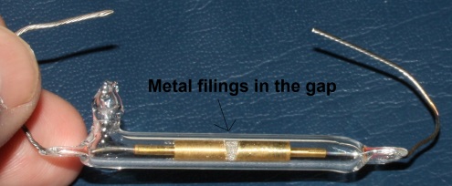 |
It has a remarkable behavior that allows us to detect radio waves. When no radio waves are present, the resistance between the electrodes is quite high. However, when a radio frequency is present, the metal filings microscopically “weld” together and the resistance drops dramatically. This behavior can be used in an electrical circuit to alert us to the presence of radio waves and it will be covered in detail below. The coherer must then be reset, which involves shaking up the filings to cause the coherer to go back to its non-conductive state, in order to detect the next signal.
Before we look at how the first receivers operated, it should be noted that they don’t have a tuner (a tuned capacitor and coil arrangement) like modern receivers.
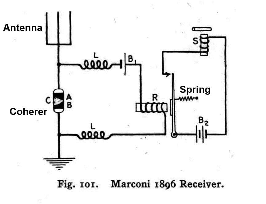 |
Instead, it uses the natural length of the antenna for tuning. The antenna can be any length but if it is ¼, ½ or 1 wavelength of the desired reception frequency then it is more effective. With such a crude tuner this receiver isn’t very selective of the signals it receives.
Here is the detailed look at how this primitive receiver operates:
1.Passing radio waves induce a voltage on the antenna. This “turns on” the coherer C because it is connected between these waves in the antenna and the ground.
2.Now that the coherer has a low resistance, electricity from the battery B1 can flow and that closes the relay R.
3.With relay R closed, the electricity from battery B2 can flow and this closes the relay S with an audible click. This click is the signal that a radio wave has been detected.
4.A spring from either of the relays is attached to the coherer so that, when the relay closes, the motion of the relay closing causes a physical jolt that resets the coherer and turns it off.
5. With the coherer reset R and S both open and the entire system is ready for the next signal.
6. The two coils L are needed to isolate the coherer and antenna from the relay coils and the electrical noise that they generate.
This type of receiver is subject to all kinds of interference such as lightning strikes and sparks from the relays within the receiver itself. It is limited to receiving pulses (like Morse code) and it is fairly “deaf” which means that the radio signals must be strong in order for it to detect them.
An upgrade to this type of receiver would be the classic crystal radio. The most difficult part of building a crystal radio from scratch would be building an extremely efficient earphone (e.g. piezoelectric earphone). Other than the earphone, you would need the crystal diode that gives the receiver its name. If you are interested in learning more, check out this page on building a crystal radio from scratch. That should be enough to get you well on your way to reinventing radio.
“Send out high frequency waves and measure how and when they bounce back and you’ve invented RADAR. Do the same with sound and oh man: SONAR.”
Reinventing RADAR, as we know it today, would require inventing a host of technologies. First, you need a very accurate clock; one accurate down to millionths of a second. Light travels 400 m (1/4 mile) in 1.3 millionths of a second so a fast clock is necessary if you want any sort of usable resolution. Second, you need a good receiver that can pick up and amplify the returning pulse and finally, you need some way to calculate the time between the outbound pulse and the inbound pulse and display that as something easy for a human to understand. The problem with using electromagnetic waves is that they are so fast. They could travel to a target 100 miles away and back 300 times in the blink of an eye. It took us until the 1930s to build electronic circuits to make radar usable.
SONAR uses sound waves which travel much slower. So in theory, you could create crude sonar by creating a ‘ping’ and let a human interpret the results. A return ping shortly after the outgoing ping would mean something close whereas a ping taking longer to return would mean something farther. One problem is that different density layers of water can deflect sound waves. Another is that not all objects or materials reflect the ping the same. I suspect that building any sort of usable sonar is going to take electronic circuitry to make sense of any return sounds. Really the question is “What do you plan to do with the RADAR or SONAR that you can’t do in another way as you rebuild civilization?”
“Mount a magnet so it can move freely, and you’ve invented the compass. Are you taking the credit? Polaris (The North Star) is just about the brightest star in the sky and it’s near the Big Dipper. Measure how high it appears to be, and the angle is your latitude.”
First, Polaris is the 45th brightest star in the sky. That’s a long way from being “Just about the brightest”. Polaris is called the North Star because it is almost directly above the North Pole. It has been used for navigation for thousands of years. Although, if you travel very far back in time Polaris wouldn’t be the star you would use to navigate. The earth has an axial precession so the star closest to the Earth’s rotation axis changes. According to Wikipedia, “In 3000 BC the faint star Thuban in the constellation Draco was the North Star… It is only one-fifth as bright as Polaris”. Either way, it is correct that you can measure how high in the sky it is to determine where you are between the North Pole and the equator (your latitude). If it is directly overhead, you are at the North Pole. If it is right on the horizon, then you are at the equator. If you are in the Southern hemisphere, it isn’t visible at all. Not sure how to find Polaris? It is described here in five ways to find north if you don’t have a compass.
Another way to measure your latitude is to record how high the sun is at noon and then compare it to a table with day of the year and how high the noon sun will be for a given latitude. Of course this requires that you have the pre-computed table.
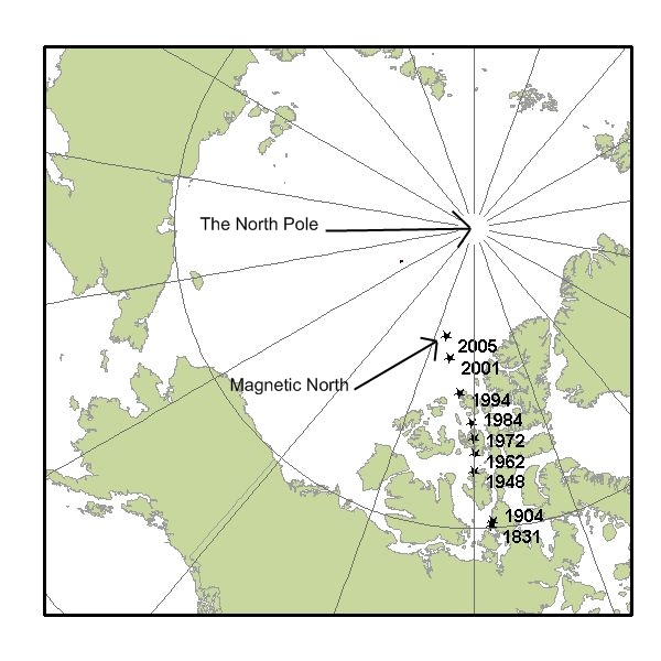 |
Inventing the compass is good but knowing how to use it is much better. Make a compass by stroking a sewing needle with some silk (or better a magnet) to magnetize the needle and then float the needle on a leaf in a bowl of water. The Earth’s iron core acts like a giant magnet and one of the ‘ends’ of the magnet is near the North Pole but not at the North Pole. One end of the needle will be attracted to it. As you can see from the illustration at right, the magnetic north pole drifts from year to year. The difference between the location of the North Pole and the location of this magnetic pole is called magnetic declination (or just declination). A compass needle aligns with the magnetic field at your location on the Earth.
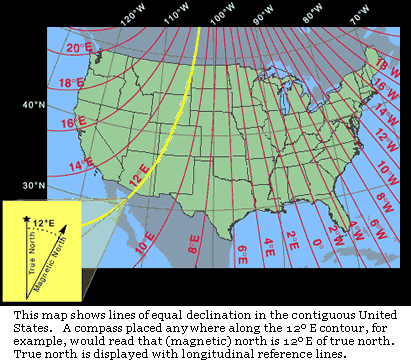 |
If you look at this map of how the declination changes across the United States, you can see that a compass needle definitely doesn’t always point north. In Northern Washington State the compass needle is pointing to a spot that is 20 degrees east of the North Pole. Actually with a self-made compass it is up to you to determine which end of the needle is North and which end represents south. If you improve your compass to have better damping and a guide to measure angles then you can use dead reckoning as a tool for map making. This article on navigation should provide you with way more than you ever wanted to know on using a compass.
“Quartz crystals are great: Run some current through them and they’ll change shape! Stop the current and they will resume their shape, and they’ll generate electricity with a very precise frequency as they do so: You can use this to build precision clocks. Nice. “
Quartz crystals are indeed awesome and essential to modern life. Their behavior is harnessed to provide oscillators that are in almost every modern electronic gadget. Cell phones, computers, televisions, transmitters, routers, microwaves, automobiles (just to name a few), all have quartz crystal oscillator circuits. It is true that electricity makes quartz crystals change shape and squashing a quartz crystal generates electricity. This is a concise summary of the piezoelectric effect that was discovered by Pierre and Jacques Curie.
What makes quartz really interesting is that it is an amazing resonator. The energy dissipated while oscillating due to internal friction is extremely small. A good tuning fork in a vacuum will complete about 2,000 cycles before it loses half of its oscillation amplitude. The best gravity pendulums will oscillate 2,000-20,000 times before losing half of their amplitude. But a quartz crystal, vibrating in a vacuum and favorably mounted, will oscillate more than a million times before falling to half amplitude. This very efficient resonating, as well as its inherent physical and chemical stability, make it very desirable as an oscillator.
As amazing as the quartz crystal is, it has to be paired with the transistor in an electronic circuit to really be useful as an oscillator. I could go into how a transistor works but so many people have already done an excellent job describing them that I will just point to them. For a general overview, check out this video from the Engineer Guy on transistors. If you have ever thought about building one from scratch, you might want to see this series of videos by Jeri Ellsworth.
“With these clocks, you can determine Longitude: Just set your clock to London time, take the difference between London Noon and local noon, and that’s how far away from the prime meridian you are. Hey! That’s longitude right there. That was easy. That deserves some credit. If you’re in 1714, the British have a 20,000 pound prize for a simple way to calculate longitude.”
As far as navigation, you really just want to know how far east or west you are of a known position. As a time traveler, knowing how far away from the prime meridian, an arbitrary starting point for modern longitude coordinates, isn’t as helpful. Plus, it would require you to have a watch set to the exact time of day on the prime meridian. Most likely you will use your starting position as your reference point because you can set your watch to the time of day at this point and you are most interested in your position relative to this point.
Figuring out how far east or west you have gone is a bit tricky. Unlike north or south, where you can measure the angle between the a star near the pole and the horizon, there is no good fixed reference for calculating how far east or west you have traveled. Instead we rely on dividing up the Earth into 24 zones (one for each hour in the day) and then use time of day to calculate our position east or west. It works like this: At the equator, the Earth is about 25,000 miles (40233.6 km) in circumference making each of the 24 hour zones 1038 miles (1670.5 km) wide. If you have an accurate watch, set to the time of your starting point, then when it is noon in your new location (as observed by the sun) you can use your watch to determine how far east or west of your starting point you are. Let’s say that difference is exactly one hour. If it is local noon but your watch shows 11:00 AM then you are 1038 miles (1670.5 km) east of your starting point. If it is local noon but your watch shows 1:00 PM then you are 1038 miles west of your starting point. This is assuming you are traveling along the equator. Another problem with longitude lines is that they converge at the poles. At the equator, 1hour west is equal to 1038 miles (1670.5 km) but if you are much farther north, like in Maine (45 degrees latitude), then 1 hour is equal to 735 miles (1182.9 km). This makes it necessary to know your latitude in order to accurately determine your longitude. It also requires an extremely accurate watch that can keep time in a variety of temperatures. The quartz watches that you could buy for a couple of dollars today, would be more accurate than the most expensive time keeping devices of the 1700s.
If you are still reading after about 10,000 words, you are probably one of the chosen few with a love for science that will repopulate the Earth after the apocalypse. I’ve only made it through the left hand side of the infographic and I’m reluctant to press on without readers to read it. Let me know what you think. Login and leave a comment. Would you like to read more?
[0] Spinal Tap movie reference. You can’t officially be part of the nerd Fight Club without having seen it.
[1] My favorite example of a ‘weird’ unit is using hands to measure the height of a horse. A hand is 4 inches (10.16 cm). What I find interesting about using hands, is that fractions of a hand are not decimal units (base 10) but base 4. Therefore 15 and ½ a hands is written as 15.2 hands and not 15.5. 15 and ¾ of a hand is written as 15.3 and 15.4 isn’t correct to because it would mean 15 hands plus 4 more inches (which is another hand). Therefore 15.4 hands is written as 16 hands.
[2] The two plaques on the Pioneer spacecraft try to establish a relative scale should they be found by another civilization. That is a tricky task when we can’t use our made up units. So we rely on schematic representation showing hydrogen, the most abundant element in the universe, flipping to its lowest energy state which causes it to emit energy at a specific frequency. The theory being that aliens advanced enough to find our spacecraft will be familiar with this phenomenon. When the distance light travels in 1 cycle of that frequency is measured, it comes out to 21.1 cm. The height of the man and woman on the plaque is related to this measurement. So even if they measure distance in zarniwhoops and time in zonkles they can still figure out how large man is because we relate it to a familiar measurement. It works because light travels at the same speed everywhere, 1 cycle is the same everywhere and the hyperfine transition of hydrogen releases the same frequency of energy everywhere.
[3] The Bernoulli principle is usually stated that faster moving air has less pressure. The Bernoulli principle is an instance of the principle of conservation of energy (which states that the total energy of the system must be conserved).
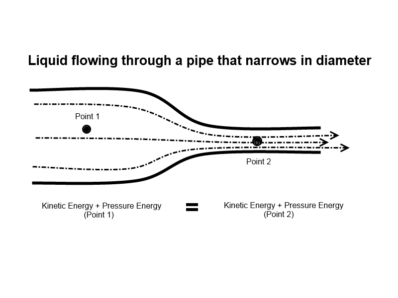 |
In this diagram, we can see that the potential energy + the kinetic energy + the pressure energy must equal the total energy (ignoring friction and assuming in-compressible fluids). The height of fluid above the ground doesn’t change from point 1 to point 2 so the potential energy term can be ignored. All we are left with is pressure energy and kinetic energy. The sum of P.E + K.E must be the same at both points 1 & 2. So any increase in the kinetic energy (like increasing velocity) must be accompanied by a corresponding decrease in pressure energy. Any decrease in kinetic energy must be accompanied by a corresponding increase in pressure energy.
[4] The equal transit time theory is usually stated something like this: “Air traveling over the airfoil must travel farther than the air traveling under the airfoil. Therefore, the air traveling over the airfoil must travel faster for the two streams to meet at the tail of the airfoil. Faster moving air has a lower pressure (Bernoulli principle) and the pressure difference with air under the wing is what causes lift.” Unfortunately, it isn’t how lift from an airfoil occurs.
[5] The Wright brothers used a slightly different lift equation. The one they used contained the Smeaton Coefficient which has a value of .00327 instead of the ( 0.5·?) term that is used in the modern lift equation. In practice that means that the that the Wright brothers used is not comparable to the Cl that is listed for modern airfoils. That’s because the lift coefficient of the modern equation is referenced to the dynamic pressure of the flow, while the lift coefficient of the Wright’s equation was referenced to the drag of an equivalent flat plate. All that really means is that Cl would be different for the same wing and the same set of flow conditions depending upon whether you were using the modern or older lift equation.
[6]Description of the test jig the Wright Brothers used goes here. It’s so cool that I think I am going to make it a stand alone article. I promise to have it written by 1 May 2013 – Ron
[7]‘Heating iron to get a weak magnet’ is referring to heating iron past its Curie point. The Curie point is the temperature at which the magnetic domains in a material are disrupted. So an iron magnet that is heated to 1,418° F (770° C) will lose its magnetism. Once it cools to below the Curie point it will regain the magnetic alignment of any magnetic field it is in (usually the magnetic field of the Earth). That’s why you can create a weak magnet by heating iron past its Curie point and allowing it to cool in a magnetic field.
References:
Flight:
Padfield, G. D. and B. Lawrence, “The birth of flight control: An engineering analysis of the Wright brothers’ 1902 glider” THE AERONAUTICAL JOURNAL December 2003: pg. 697-718. Print www.Pcwww.liv.ac.uk/eweb/fst/publications/2854.pdf
Abzug , Maclom J. and E. Eugene Larrabee, “Airplane Stability and Control, Second Edition – A History of Technologies That Made Aviation Possible” Cambridge UK, Cambridge University Press 2002, Print http://assets.cambridge.org/97805218/09924/sample/9780521809924ws.pdf
Sadraey, Mohammad “Aircraft Design: A Systems Engineering Approach (Aerospace Series) Chapter 5-Wing design” Wiley; 1 edition 2012, Print http://faculty.dwc.edu/sadraey/Chapter%205.%20Wing%20Design.pdf
Culick, Fred E. C. and Henry R. Jex, “Aerodynamics, Stability and Control of the 1903 Wright Flyer”, AIAA 1984, http://authors.library.caltech.edu/21217/1/CULaiaawfp84.pdf
Denker, John S. “See how it flies”, Web. http://www.av8n.com/how/#contents
Heintz , Chris “Anatomy of a STOL Aircraft: Designing a Modern Short Take-Off and Landing Aircraft”, Web, http://www.zenithair.com/stolch801/design/design.html
Pasteurization & Canning:
“Grade A Pasteurized Milk Ordinance 2009 Revision”. US Dept of Health and Human Services.
Schneider, Keith R., Chang, Alexandra and Goodrich, Renée M., “Preventing Foodborne Illness: Clostridium botulinum” University of Florida IFAS Extension, publication #FSHN0406. Print http://edis.ifas.ufl.edu/fs104
National Center for home food preservation, Websire http://nchfp.uga.edu/
Radio:
Hawkins, Jim “Electromagnetic Radiation Explained” , Spetember 2003, Web, http://www.hawkins.pair.com/eRadiation.html
Ceperley, Peter “Resonances, Waves, Fields and their Applications, Physics and math”, June 2007, Web http://resonanceswavesandfields.blogspot.com/2007_06_01_archive.html
Fuhring, John “AN EARLY COHERER RADIO RECEIVER CIRCA 1898”, Webhttp://www.geojohn.org/Radios/MyRadios/Coherer/Coherer.html
“Building a Crystal Radio out of Houshold Items”, Website http://scitoys.com/scitoys/scitoys/radio/homemade_radio.html
Quartz:
Crane, H. Richard, “The Quartz Analog Watch: A Wonder Machine” , The Physics Teacher, Vol 31, Nov 1999, Pg 501. Print Link http://www.engineerguy.com/videos/learn-more/physics-teacher-crane-quartz.pdf
Marrison, Warren A. “”The Evolution of the Quartz Crystal Clock”, The Bell System Technical Journal, Vol. XXVII, pp. 510-588, 1948, Print http://www.ieee-uffc.org/main/history.asp?file=marrison
Vig, John R.” QUARTZ CRYSTAL RESONATORS AND OSCILLATORS For Frequency Control and Timing Applications A Tutorial”, U.S. Army Communications-Electronics Command, Web, http://www.am1.us/Local_Papers/U11625%20VIG-TUTORIAL.pdf
Bertrand, Ron, “Online Radio & Electronic Course – Oscillators” , Web http://arcarc.xmission.com/PDF_Electronics/Oscillators.pdf
Longitude & Navigation:
Tyson, Peter, “Secrets of Ancient Navigators”, PBS -Nova, October 1998, Website http://www.pbs.org/wgbh/nova/ancient/secrets-of-ancient-navigators.html